RENEWLab consists of a set of three different frameworks for running wireless experiments utilizing Iris Software Defined Radios:
- Sounder: C++ based framework for rapid collecting of channel traces (real-time data collection + post-processing of data)
- Python-based collection of Demo scripts and analysis tools (including analysis of channel traces collected via Sounder)
- Matlab-based collection of Demo scripts for transmitting, receiving, and analyzing waveforms (both for single- and multi-antenna setups)
Next, we present a step-by-step description of how to get started with RENEWLab.
¶ 0. Pre-Requisites
RENEWLab can be used by researchers of various levels of experience. We recommend the following “minimum background” for each of the different RENEWLab tools:
¶ Sounder
- Running Sounder for data collection (no code modifications involved).
- Intermediate knowledge of wireless communications.
- Basic knowledge of Linux and command-line interface (CLI).
- Basic knowledge of Python for post-processing of collected channel traces.
- Familiar with JSON file format (used for configuration).
- Familiar with Git.
- Modifying Sounder code.
- Intermediate knowledge of wireless communications.
- Intermediate knowledge of Linux and command-line interface (CLI).
- Intermediate to advanced knowledge of C++ (depending on the extent of the modifications needed).
- Familiar with Git.
¶ Python Scripts
- Intermediate knowledge of wireless communications.
- Basic knowledge of Linux and command-line interface (CLI).
- Intermediate knowledge of Python, including Numpy and Matplotlib libraries.
- Familiar with Git.
¶ Matlab Scripts
- Intermediate knowledge of wireless communications.
- Basic knowledge of Linux and command-line interface (CLI).
- Intermediate knowledge of Matlab.
- Familiar with Git.
¶ 1. Recommended Setup (NOTE for POWDER users: Please skip steps 1 and 2)
TBD
¶ 2. Clone RENEWLab Repository
For those running RENEWLab software locally on their own machines or in some server where the RENEW software has not been installed (i.e., non-POWDER users), you will need to clone the RENEWLab repository and install all the dependencies yourselves.
First, clone the repository and go into the main directory:
git clone https://github.com/renew-wireless/RENEWLab.git
cd RENEWLab/Next, run the following three scripts located inside the RENEWLab directory:
- Install SoapySDR software and Iris drivers:
./install_soapy.sh - Install RENEWLab Python dependencies and packages:
./install_pylibs.sh - Install RENEWLab Real-time C++ software dependencies:
./install_cclibs.sh
If you are planning on using the Sounder tool, you first must build the code, as shown below:
cd CC/Sounder/mufft/
git submodule update --init
cmake -DCMAKE_POSITION_INDEPENDENT_CODE=ON ./ && make -j
cd ../
mkdir build
cd build
cmake .. -DCMAKE_BUILD_TYPE=Release -DLOG_LEVEL=info && make -j
cd ../This will first build and link another dependency (mufft) that is included as a git submodule, and then it will compile the Sounder code. The build process generates an executable under the build folder, called sounder.
¶ 3. Checking Massive MIMO Board Topology
Users can easily check the boards that are available and how they are connected within each base station.
To do so, you need to run the following command
python3 -m pyfaros.discoverIf the Pyfaros tools are not installed in your system, you can install them as follows:
git clone --branch v1.4 --depth 1 --single-branch https://github.com/skylarkwireless/pyfaros.git
cd pyfaros/
./create_package.sh
cd dist && pip3 install *.tar.gz --ignore-installedor the following for Ubuntu 22.04
git clone --branch python310_updates --depth 1 --single-branch https://github.com/Agora-wireless/pyfaros || \
    { echo "Failed to clone git repository: $PYFAROS" && exit 1; }
cd pyfaros/
./create_package.sh
pyfaros_version=`./create_version.sh`
cd dist
pip3 install pyfaros-${pyfaros_version}.tar.gz --force-reinstall || \
    { echo "Failed to install Pyfaros!" && exit 1; }
The output of the python3 -m pyfaros.discover should look something like the image below. The screenshot shows the Hub's serial number or ID (i.e., FH4B000021) as well as the base station configuration. Each ‘Chain’ shows a different Remote Radio Head (RRH) and its serial number (e.g., RF6A000010 in Chain1), and the boards within that specific RRH (e.g., 246, 490, 749, 697). Notice this base station has one hub, six RRHs (ignore the duplicates in the Chain numbering), four Iris boards in each RRH.
Finally, at the bottom it might list the available ‘Standalone Clients’ (e.g., 119, 145).
pc1:~$ python3 -m pyfaros.discover
Topology at 2021-06-23 14:08:43.582116
├── Hub: FH4B000021    192.168.1.142 - FW: 2021.05.0.0-18-5d9c655 FPGA: 2021.05.0.0-5d9c655-sdr
│   ├── Chain 1  Serial RH6A000010  Count 4  FW 2021.05.0.0-18-5d9c655 FPGA 2021.05.0.0-5d9c655-sdr
│   │   ├── Iris 1:RF3E000246 - 192.168.1.109                 - FW: 2021.05.0.0-18-5d9c655 FPGA: 2021.05.0.0-5d9c655-sdr
│   │   ├── Iris 2:RF3E000490 - 192.168.1.112                 - FW: 2021.05.0.0-18-5d9c655 FPGA: 2021.05.0.0-5d9c655-sdr
│   │   ├── Iris 3:RF3E000749 - 192.168.1.124                 - FW: 2021.05.0.0-18-5d9c655 FPGA: 2021.05.0.0-5d9c655-sdr
│   │   └── Iris 4:RF3E000697 - 192.168.1.117                 - FW: 2021.05.0.0-18-5d9c655 FPGA: 2021.05.0.0-5d9c655-sdr
│   ├── Chain 1  Serial RH6A000019  Count 4  FW 2021.05.0.0-18-5d9c655 FPGA 2021.05.0.0-5d9c655-sdr
│   │   ├── Iris 5:RF3E000724 - 192.168.1.106                 - FW: 2021.05.0.0-18-5d9c655 FPGA: 2021.05.0.0-5d9c655-sdr
│   │   ├── Iris 6:RF3E000740 - 192.168.1.121                 - FW: 2021.05.0.0-18-5d9c655 FPGA: 2021.05.0.0-5d9c655-sdr
│   │   ├── Iris 7:RF3E000532 - 192.168.1.123                 - FW: 2021.05.0.0-18-5d9c655 FPGA: 2021.05.0.0-5d9c655-sdr
│   │   └── Iris 8:RF3E000716 - 192.168.1.113                 - FW: 2021.05.0.0-18-5d9c655 FPGA: 2021.05.0.0-5d9c655-sdr
│   ├── Chain 2  Serial RH6A000018  Count 4  FW 2021.05.0.0-18-5d9c655 FPGA 2021.05.0.0-5d9c655-sdr
│   │   ├── Iris 1:RF3E000674 - 192.168.1.102                 - FW: 2021.05.0.0-18-5d9c655 FPGA: 2021.05.0.0-5d9c655-sdr
│   │   ├── Iris 2:RF3E000704 - 192.168.1.114                 - FW: 2021.05.0.0-18-5d9c655 FPGA: 2021.05.0.0-5d9c655-sdr
│   │   ├── Iris 3:RF3E000676 - 192.168.1.103                 - FW: 2021.05.0.0-18-5d9c655 FPGA: 2021.05.0.0-5d9c655-sdr
│   │   └── Iris 4:RF3E000668 - 192.168.1.125                 - FW: 2021.05.0.0-18-5d9c655 FPGA: 2021.05.0.0-5d9c655-sdr
│   ├── Chain 3  Serial RH6A000011  Count 4  FW 2021.05.0.0-18-5d9c655 FPGA 2021.05.0.0-5d9c655-sdr
│   │   ├── Iris 1:RF3E000340 - 192.168.1.107                 - FW: 2021.05.0.0-18-5d9c655 FPGA: 2021.05.0.0-5d9c655-sdr
│   │   ├── Iris 2:RF3E000744 - 192.168.1.115                 - FW: 2021.05.0.0-18-5d9c655 FPGA: 2021.05.0.0-5d9c655-sdr
│   │   ├── Iris 3:RF3E000161 - 192.168.1.116                 - FW: 2021.05.0.0-18-5d9c655 FPGA: 2021.05.0.0-5d9c655-sdr
│   │   └── Iris 4:RF3E000735 - 192.168.1.104                 - FW: 2021.05.0.0-18-5d9c655 FPGA: 2021.05.0.0-5d9c655-sdr
│   ├── Chain 3  Serial RH6A000016  Count 4  FW 2021.05.0.0-18-5d9c655 FPGA 2021.05.0.0-5d9c655-sdr
│   │   ├── Iris 5:RF3E000387 - 192.168.1.108                 - FW: 2021.05.0.0-18-5d9c655 FPGA: 2021.05.0.0-5d9c655-sdr
│   │   ├── Iris 6:RF3E000389 - 192.168.1.126                 - FW: 2021.05.0.0-18-5d9c655 FPGA: 2021.05.0.0-5d9c655-sdr
│   │   ├── Iris 7:RF3E000206 - 192.168.1.120                 - FW: 2021.05.0.0-18-5d9c655 FPGA: 2021.05.0.0-5d9c655-sdr
│   │   └── Iris 8:RF3E000211 - 192.168.1.111                 - FW: 2021.05.0.0-18-5d9c655 FPGA: 2021.05.0.0-5d9c655-sdr
│   └── Chain 4  Serial RH6A000017  Count 4  FW 2021.05.0.0-18-5d9c655 FPGA 2021.05.0.0-5d9c655-sdr
│       ├── Iris 1:RF3E000256 - 192.168.1.110                 - FW: 2021.05.0.0-18-5d9c655 FPGA: 2021.05.0.0-5d9c655-sdr
│       ├── Iris 2:RF3E000383 - 192.168.1.118                 - FW: 2021.05.0.0-18-5d9c655 FPGA: 2021.05.0.0-5d9c655-sdr
│       ├── Iris 3:RF3E000304 - 192.168.1.122                 - FW: 2021.05.0.0-18-5d9c655 FPGA: 2021.05.0.0-5d9c655-sdr
│       └── Iris 4:RF3E000303 - 192.168.1.119                 - FW: 2021.05.0.0-18-5d9c655 FPGA: 2021.05.0.0-5d9c655-sdr
└── Standalone Clients
    └── Iris Count: 2  FW 2021.05.0.0-18-5d9c655 FPGA 2021.05.0.0-5d9c655-ue
        ├── Iris :RF3E000119 - 192.168.1.138                 - FW: 2021.05.0.0-18-5d9c655 FPGA: 2021.05.0.0-5d9c655-ue
        └── Iris :RF3E000145 - 192.168.1.130                 - FW: 2021.05.0.0-18-5d9c655 FPGA: 2021.05.0.0-5d9c655-ue
NOTE: Run the command twice to ensure the system is able to detect and show the topology correctly. There is a known issue related to board discovery that makes it fail occasionally. If after a couple of tries it does not work, then something has gone wrong and someone in the team will have to look into it. Please reach out to us at support@renew-wireless.org if this happens.
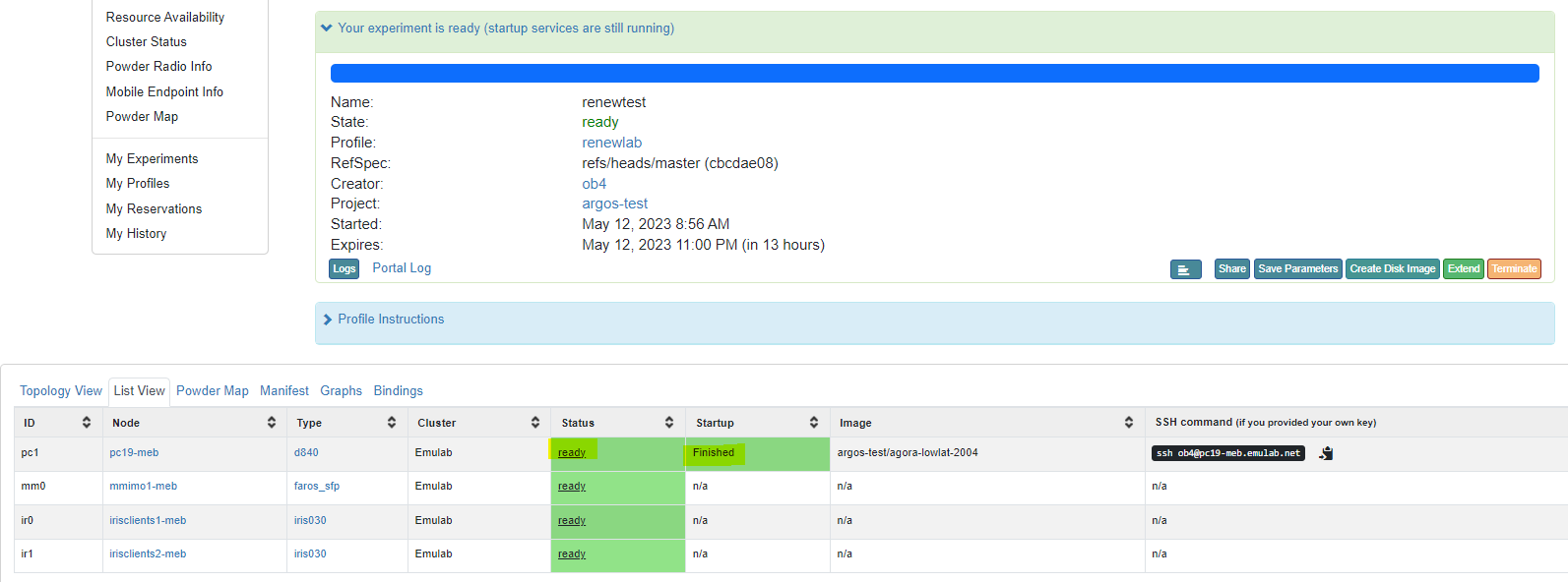
NOTE FOR POWDER USERS: It might take a few minutes for this command to work right after the experiment instantiation. If it doesn't work right away, give it a couple of minutes. Even though the experiment has started, there are certain initialization scripts that continue to run a few minutes after the experiment becomes available. You can always check the status under the “topology” or “list view” tabs:

¶ 4. Run Demos
Here we provide a basic overview of how to run the Sounder, and some simple scripts written in Python and Matlab. For more details on each framework please refer to the Software Architecture Section. The software architecture page contains more information on the available software, including step-by-step tutorials on using the Massive MIMO equipment. Here we simply show how to run some of the RENEWLab tools.
4.1. Channel Sounding
The Sounder is a C++-based framework that allows users to configure RENEW clients to transmit uplink pilots and user-defined data signals to the base station and to record the received signals from all base station antennas to HDF5 datasets in real time. The pilot signals are transmitted in a time-orthogonal fashion from each configured client and uplink signals are sent at common subframes by all clients. These pilot and data signals are recorded as multi-dimensional matrices in separate datasets in the HDF5 file. Dataset analysis tools are developed in Python3 that enable the plotting of signals at various dimensions and calculation of various statistics of the massive MIMO channel as well as offline demultiplexing of the uplink signals.
The sounder code runs in a host machine (e.g., a server or your own local PC) and communicates with the SDR hardware via the SoapySDR library. The Sounder takes a JSON-formatted configuration file as input. Example config files can be found under the /Sounder/files directory, e.g., Sounder/files/powder-1u-pilot.json:
{
        "serial_file" : "files/topology-meb-1u.json",
        "frequency" : 3.545e9,
        "sample_rate" : 5e6,
        "channel" : "AB",
        "rx_gain_a" : 65,
        "tx_gain_a" : 60,
        "rx_gain_b" : 65,
        "tx_gain_b" : 60,
        "frame_schedule" : [
                "BGPPGGGGGGGGGGGGGGGG"
        ],
        "max_frame" : 4000,
        "ofdm_symbol_per_slot" : 10,
        "fft_size" : 64,
        "cp_size" : 16,
        "ofdm_tx_zero_prefix" : 160,
        "ofdm_tx_zero_postfix" : 160,
        "beamsweep" : true,
        "ue_channel" : "AB",
        "ue_rx_gain_a" : [65],
        "ue_tx_gain_a" : [81],
        "ue_rx_gain_b" : [65],
        "ue_tx_gain_b" : [81],
        "ue_frame_schedule" : [
                "GGPPGGGGGGGGGGGGGGGG"
        ],
        "tx_advance" : [135]
}
This file is used to configure the mMIMO base station and a single client. For more details on the different configuration parameters shown here, please refer to our extensive Sounder guide.
The serial numbers of the nodes in the base station are read from a different JSON file (a <topology-filename>.json) under the /files directory. If using POWDER, the startup scripts will generate this file automatically. Otherwise, users will have to go into the /files directory and run the command:
python3 -m pyfaros.discover --json-outThis will generate the topology.json file, which contains topology information in the following format:
{
    "BaseStations": {
        "BS0": {
            "hub": "FH4B000019",
            "rrh": [
                "RH3B000001",
                "RH3B000020",
                "RH3B000010",
                "RH3B000004",
                "RH3B000002"
            ],
            "sdr": [
                "RF3E000356",
                "RF3E000546",
                "RF3E000620",
                "RF3E000609",
                "RF3E000604",
                "RF3E000612",
                "RF3E000640",
                "RF3E000551",
                "RF3E000208",
                "RF3E000636",
                "RF3E000632",
                "RF3E000568",
                "RF3E000558",
                "RF3E000633",
                "RF3E000566",
                "RF3E000635"
            ],
            "reference": "RF3E000089"
        }
    },
    "Clients": {
        "sdr": [
            "RF3E000068"
        ]
    }
}If running Sounder with a configuration file that only uses one single client, you will need to make sure your JSON topology file only lists one client as well, otherwise, it will throw an error. You can simply keep one client and delete the rest (remove any comma left after the single serial in the list).
All Base station devices are listed under “BaseStations”:
- BSX: We use the term ‘BS’ to refer to each individual base station. If multiple base stations are instantiated, multiple BSs will be listed.
- hub: Each base station has at least one hub to which all different SDR chains are connected to.
- rrh: Each base station will have multiple radio heads (remote radio heads or RRH), each containing several SDRs. This is optional and for future use.
- sdr: List of all the SDR devices found.
- reference: Some base stations will have a reference node that is used for intra-base station measurements such as reciprocity calibration.
All client device information is listed under “Clients”:
If users wish to know the exact topology (e.g., which SDR belongs to which RRH), they can simply run the command python3 -m pyfaros.discover without passing the --json-out flag. NOTE: Due to a limitation in the board discovery process, the command might fail from time to time so users might need to run it twice.
Finally, we can run the Sounder as follows:
$ ./build/sounder -conf_file files/powder-1u-pilot.json
This will generate an HDF5 file that contains not only raw IQ samples but also metadata with the different parameters used in the experiment. This file will be saved under the /Sounder/logs/ directory.
Users can analyze the contents of the file by using a Python script we provide. To run it:
python3 ../../PYTHON/IrisUtils/plot_hdf5.py ./logs/<filename>.hdf5This will output a couple of different plots showing the pilots sent from the client to the base station. Alternatively, users can run the plot_hdf5.py passing different flags to do a more in-depth analysis or to focus on specific frames/antennas:
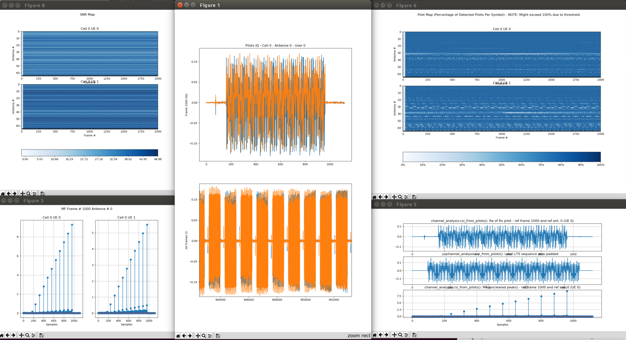
python3 ../../PYTHON/IrisUtils/plot_hdf5.py ./logs/<filename>.hdf5 --deep-inspectThis command will show several plots like the following:
To get a list of the flags that can be used with the script, you can pass it the --help keyword:
python3 ../../PYTHON/IrisUtils/plot_hdf5.py ./logs/<filename>.hdf5 --helpIf there are no plots showing up, it may be due to a couple of reasons:
- Issues with X11 forwarding. Make sure your system is configured correctly and X11 forwarding is enabled. See our ‘Common Issues’ page on this.
- The Python script will show a message saying no good Pilots/Data were found. If this is the case, you can try to lower the detection threshold by passing another value lower than the default (
--thresh), or more likely, the gains you used in the experiment were too low (signal not strong enough) or too high (saturation). You can play around with the gains, using values around 60 or 70 for both TX and RX, as a starting point.
¶ 4.2. Beamsweeping
Python Scripts: BEACON_SWEEP.py and SISO_RX.py
Description: Script for generating beacons and precoding signals to create a beamsweep. Beacon can ONLY be generated by base station boards (not clients). The BEACON_SWEEP.py script deals only with the transmitter side. In other words, the script generates and transmits the beacons. A receiver scripts such as SISO_RX.py can be used on the receiver (client), to capture the beamsweeped beacons.
Instructions: Run python3 BEACON_SWEEP.py --serials="RF3E000xxx","RF3E000yyy" --freq=<freq. in Hz> on one terminal. Here, "RF3E000xxx" and "RF3E000yyy" are the serials of two Iris boards on the base station. You can add as many boards as they are available for each base station. Notice there are no spaces between the serial numbers. Open another terminal and run python3 SISO_RX.py --serial="RF3E000zzz" --freq=<freq. in Hz>.
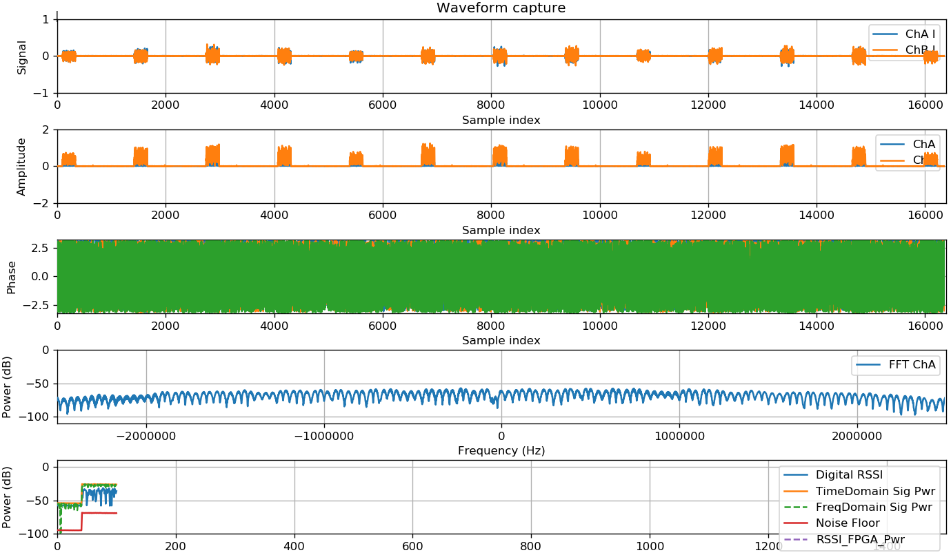
The picture below shows the output of the receivers script. This result was obtained inside the anechoic chamber at POWDER, at 3.6 GHz, and using only 4 boards on the base station (using default gains).
¶ 4.3. Single-Input Single-Output (SISO)
Matlab Scripts: rl_ofdm_siso.m
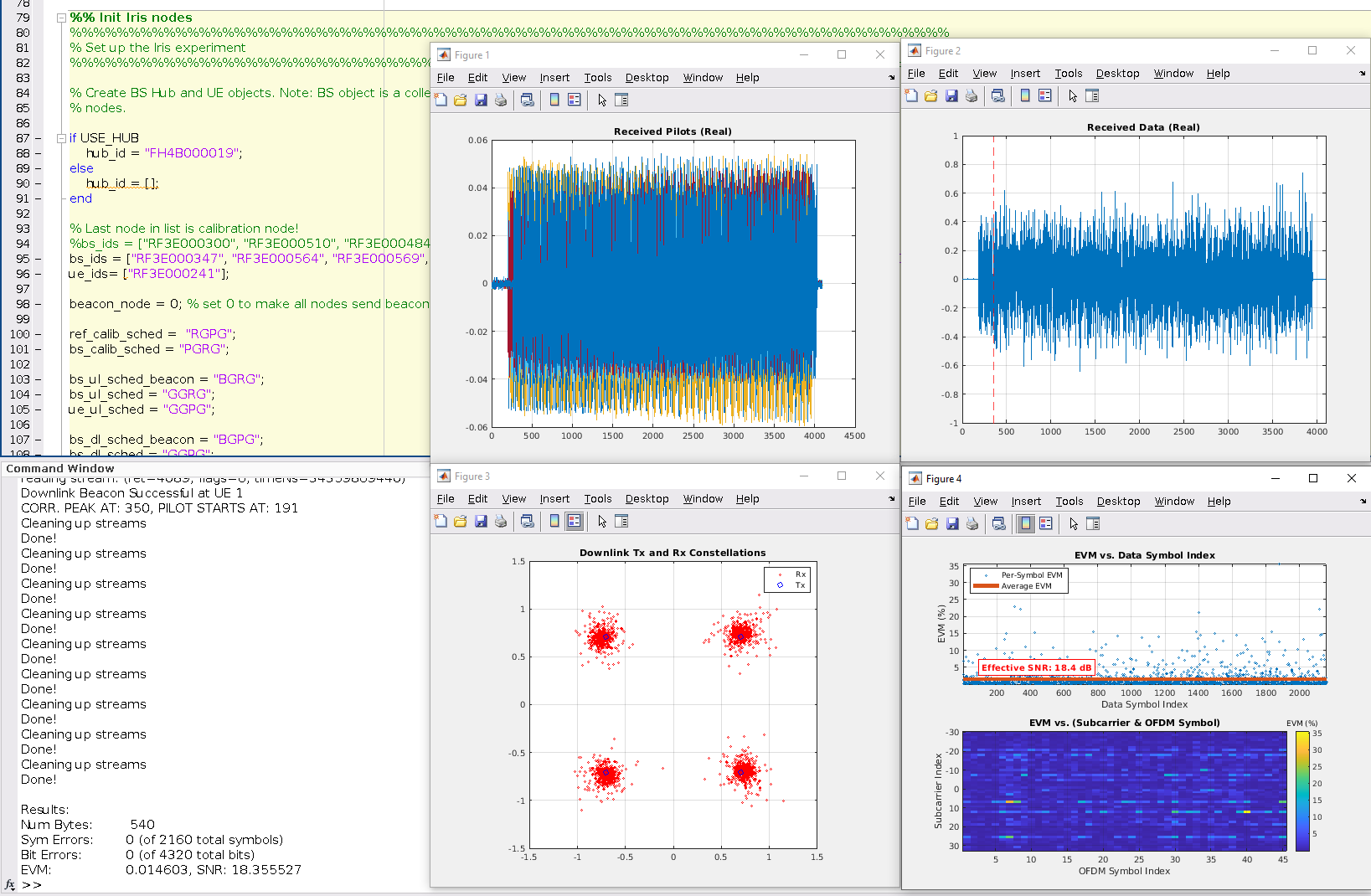
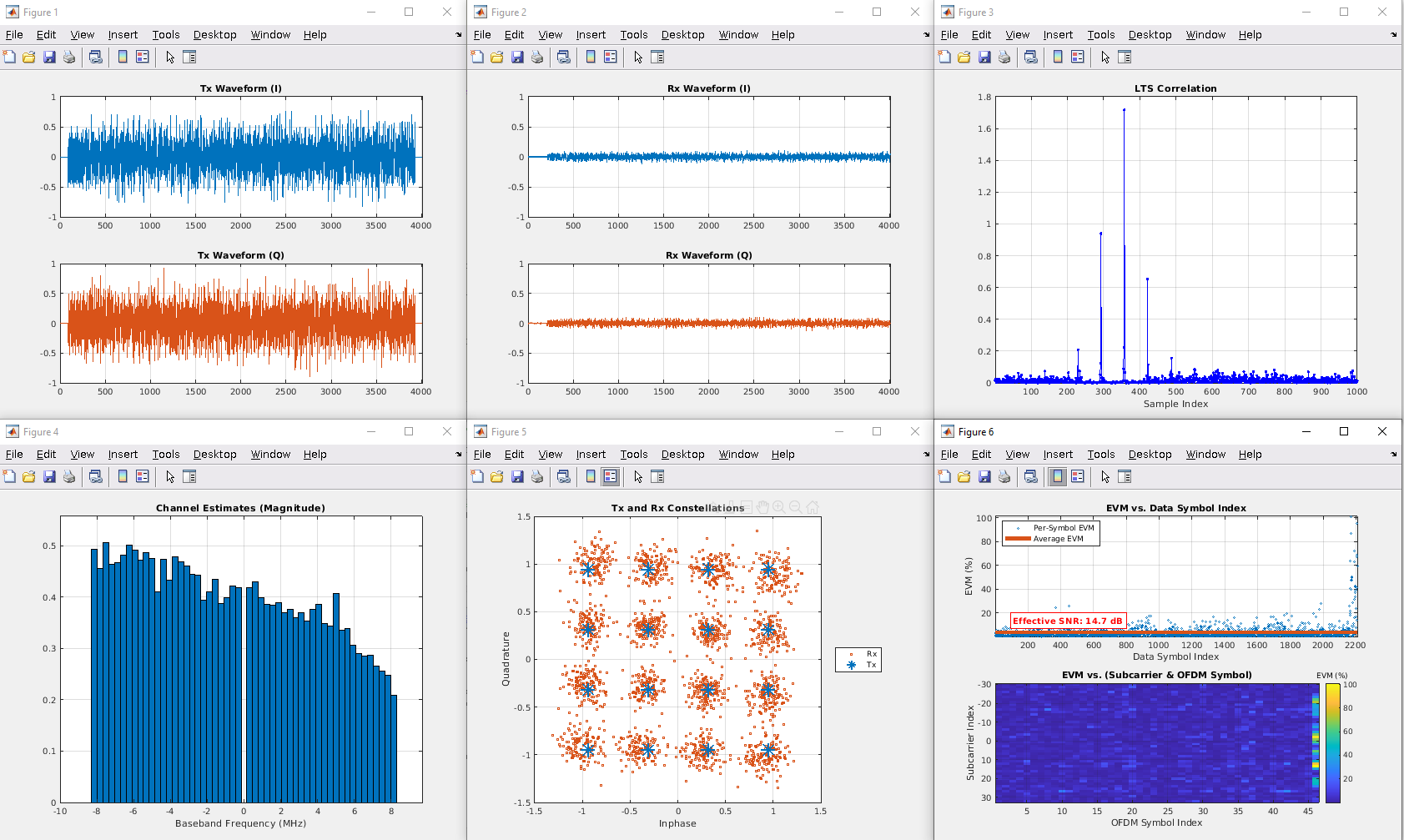
Description: Multiple iterations of a single-shot transmissions from one client or UE to one base station radio (UE stands for User Equipment). The script explores Bit Error Rate (BER) as a function of Signal-to-Noise Ratio (SNR) and therefore iterates over different SNR values (sim_SNR_db variable). Within each iteration, only a single frame transmission takes place. We define two modes: OTA (Over-the-air) and SIM_MOD (simulation). In simulation mode we simply use a Rayleigh channel whereas the OTA mode relies on the Iris hardware for transmission and reception. In both cases the client transmits an OFDM signal that resembles a typical 802.11 WLAN waveform. If the transmission is OTA, then the user specifies a schedule that tells the client when to transmit its frame. The base station initiates the schedule by sending a beacon signal that synchronizes the client. After that, the client will simply transmit its frame. Here's what users should expect to see when they run this script.
Instructions: Change the serial numbers of the boards you want to use. The script is currently configured for the anechoic chamber setup on POWDER so it will fail if you try to run it using the boards on the outdoor deployment. You may also need to adjust the gains according to the distance between the transmitter and receiver. We typically stay within the following ranges (although not necessarily):
TxGains: [55 to 81] dB
RxGains: [50 to 75] dB
Other than that, simply run the script.
Note: If running Matlab on the POWDER platform, you'll have to launch matlab from /usr/local/MATLAB/ folder.
¶ 4.4. Uplink mMIMO Single-User
Matlab Scripts: rl_ofdm_simo.m
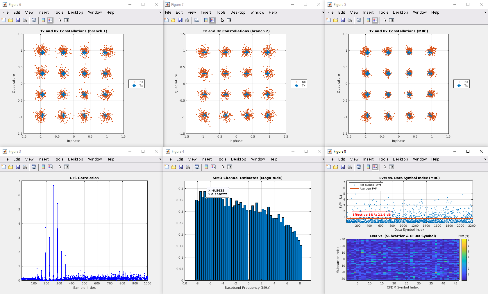
Description: Multiple iterations of a single-shot transmissions from one client or UE to N_BS_NODE base station radios (UE stands for User Equipment). The script explores Bit Error Rate (BER) as a function of Signal-to-Noise Ratio (SNR) and therefore iterates over different SNR values (sim_SNR_db variable). Within each iteration, only a single frame transmission takes place. We define two modes: OTA (Over-the-air) and SIM_MOD (simulation). In simulation mode we simply use a AWGN channel whereas the OTA mode relies on the Iris hardware for transmission and reception. In both cases the client transmits an OFDM signal that resembles a typical 802.11 WLAN waveform. If the transmission is OTA, then the user specifies a schedule that tells the client when to transmit its frame. The base station initiates the schedule by sending a beacon signal that synchronizes the client. After that, the client will simply transmit its frame.
Instructions: Change the serial numbers of the boards you want to use. The script is currently configured for the anechoic chamber setup on POWDER so it will fail if you try to run it using the boards on the outdoor deployment. You may also need to adjust the gains according to the distance between the transmitter and receiver. We typically stay within the following ranges (although not necessarily):
TxGains: [55 to 81] dB
RxGains: [50 to 75] dB
Other than that, simply run the script.
Note: If running Matlab on the POWDER platform, you'll have to launch matlab from /usr/local/MATLAB/ folder.
¶ 4.5. Uplink mMIMO Multi-User
Matlab Scripts: rl_ofdm_mimo.m
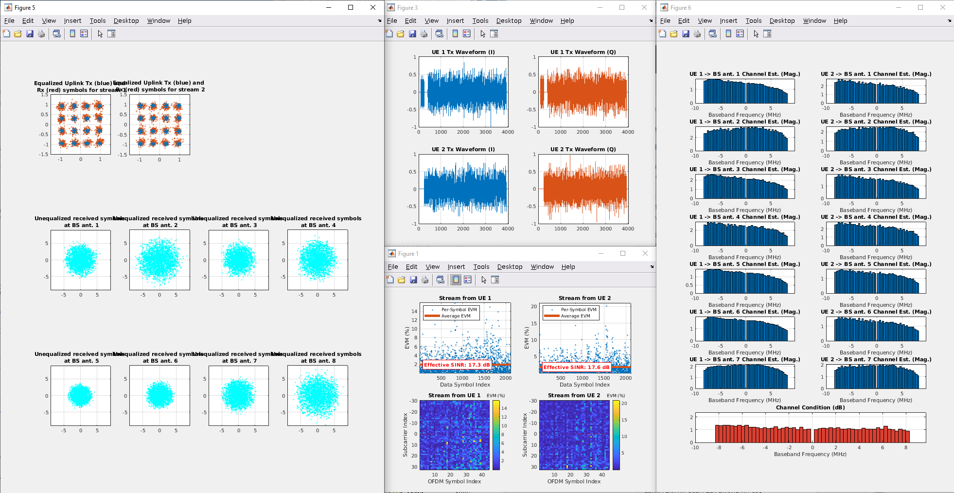
Description: Single-shot transmission from N_UE clients to N_BS_NODE base station radios (UE stands for User Equipment). We define two modes: OTA (Over-the-air) and SIM_MOD (simulation). In simulation mode we simply use a Rayleigh channel whereas the OTA mode relies on the Iris hardware for transmission and reception. In both cases the clients transmit an OFDM signal that resembles a typical 802.11 WLAN waveform. If the transmission is OTA, then the user specifies a schedule that tells all clients when to transmit their frame The base station initiates the schedule by sending a beacon signal that synchronizes clients. After that, all clients will transmit simultaneously. We implement a frame structure that allows the base station to capture clean (non-overlapping) training sequences for equalization and demultiplexing of the concurrent data streams.
Instructions: Change the serial numbers of the boards you want to use. The script is currently configured for the anechoic chamber setup on POWDER so it will fail if you try to run it using the boards on the outdoor deployment. You may also need to adjust the gains according to the distance between the transmitter and receiver. We typically stay within the following ranges (although not necessarily):
TxGains: [55 to 81] dB
RxGains: [50 to 75] dB
Other than that, simply run the script.
Note: If running Matlab on the POWDER platform, you'll have to launch matlab from /usr/local/MATLAB/ folder.
4.6. Downlink mMIMO Single-User
Matlab Scripts: rl_ofdm_downlink_miso.m
Description: Single-shot transmission from N_BS_NODE base station radios to a single UE or client (UE stands for User Equipment). We define two modes: OTA (Over-the-air) and SIM_MOD (simulation). In simulation mode we simply use a Rayleigh channel whereas the OTA mode relies on the Iris hardware for transmission and reception. In both cases the clients transmit an OFDM signal that resembles a typical 802.11 WLAN waveform. If the transmission is OTA, then the user specifies a set of schedules that tell all clients and base station boards when to transmit their frames. Unlike the other demo scripts, this one defines three different schedules:
1.- Calibration: The first step is to perform reciprocity calibration
2.- Uplink pilots: The base station initiates the schedule by sending a beacon signal that synchronizes clients. After that, the client will transmit its pilot signal. This pilot will be used by the base station to compute the downlink beamforming weights.
3.- Downlink data: Using the beamforming weights, the base station precodes the data for the user and triggers a downlink beamformed transmission.
Instructions: Change the serial numbers of the boards you want to use. The script is currently configured for the anechoic chamber setup on POWDER so it will fail if you try to run it using the boards on the outdoor deployment. You may also need to adjust the gains according to the distance between the transmitter and receiver. We typically stay within the following ranges (although not necessarily):
TxGains: [55 to 81] dB
RxGains: [50 to 75] dB
Other than that, simply run the script.
Note: If running Matlab on the POWDER platform, you'll have to launch matlab from /usr/local/MATLAB/ folder.
